the Creative Commons Attribution 4.0 License.
the Creative Commons Attribution 4.0 License.
 | 23 Sep 2021
Land-based wind turbines with flexible rail-transportable blades – Part 1: Conceptual design and aeroservoelastic performance
Pietro Bortolotti
Nick Johnson
Nikhar J. Abbas
Evan Anderson
Ernesto Camarena
Joshua Paquette
This work investigates the conceptual design and the aeroservoelastic performance of land-based wind turbines whose blades can be transported on rail via controlled bending. The turbines have a nameplate power of 5 MW and a rotor diameter of 206 m, and they aim to represent the next generation of land-based machines. Three upwind designs and two downwind designs are presented, combining different design goals together with conventional glass and pultruded carbon fiber laminates in the spar caps. One of the five blade designs is segmented and serves as a benchmark to the state of the art in industry. The results show that controlled flexing requires a reduction in the flapwise stiffness of the blades, but it represents a promising pathway for increasing the size of land-based wind turbine rotors. Given the required stiffness, the rotor can be designed either downwind with standard rotor preconing and nacelle uptilt angles or upwind with higher-than-usual angles. A downwind-specific controller is also presented, featuring a cut-out wind speed reduced to 19 m s−1 and a pitch-to-stall shutdown strategy to minimize blade tip deflections toward the tower. The flexible upwind and downwind rotor designs equipped with pultruded carbon fiber spar caps are found to generate the lowest levelized cost of energy, 2.9 % and 1.3 %, respectively, less than the segmented design. The paper concludes with several recommendations for future work in the area of large flexible wind turbine rotors.
- Article
(1710 KB) - Full-text XML
- Companion paper
- BibTeX
- EndNote


Wind energy today is one of the most cost-competitive sources of electricity. The recent reduction in the levelized cost of energy (LCOE) for wind has been possible thanks to various factors, among which is a continuous increase in turbine size. In terms of cost per kilowatt, larger machines help decrease balance-of-station costs in addition to operation-and-maintenance costs. An increasingly robust supply chain has led to fairly constant values of turbine capital costs per kilowatt, whereas larger rotors and taller towers increase annual energy production (AEP). The larger rotor-swept areas have also helped to increase power generation at low wind speeds, which is especially attractive in markets that are dominated by wind energy. Here, electricity price is often inversely proportional to wind speed, which has pushed the technology trends toward larger rotor diameters and lower values of specific power. Low specific power also allows for better predictability of power production, ultimately supporting a higher share of renewables in the energy mix (Bolinger et al., 2020).
The increasing size of wind turbines is clearly visible in offshore platforms – for example, the latest 15 MW reference wind turbine of International Energy Agency (IEA) Wind Task 37 mounts a rotor of 240 m in diameter at a hub height of 150 m above mean sea level (Gaertner et al., 2020). Land-based wind turbines have also been increasing in size, but the trend has been less aggressive than offshore. The main reason behind this difference can be explained by the rigid transportation constraints that land-based installations must meet. A first set of constraints has traditionally impacted the tower size because conventional steel towers cannot exceed base diameters of 4.5 m for road transport. Recently, however, alternative technologies – such as hybrid concrete–steel towers, field-welded towers, and self-erecting towers – have offered promising pathways for overcoming these limits (Dykes et al., 2018). A second set of constraints impacts the design of the blades, with stringent limits on the maximum chord, prebend, sweep, and length. The first three quantities are constrained to have the blade fit within a rectangular clearance section. A common value for the maximum chord is 4.75 m, and this limit is usually respected by imposing aerodynamically suboptimal chord values as well as flat-back and truncated airfoils. Prebend is often constrained to 3 or 4 m at the blade tip, and designers increase rotor cone and nacelle tilt angles to reach sufficient blade-tower clearance. For sweep, only a few manufacturers adopt it in their blade designs, and the curvature is always limited to no more than a few meters to limit the growth in blade torsional moment, which impacts the design of the pitch system (Bortolotti et al., 2019b). Although these constraints do not necessarily represent hard stops to the growth in turbine size, the logistical limit on blade length is harder to address. Logistics companies have broken several barriers during the past years, but the longest monolithic blades currently being transported on land are still limited to 70–75 m. One technological solution to overcome this limitation consists of segmenting the blade into two parts, where the inner part is as long as it can be transported and the outer part is as long as the joint can support. Although they are promising and commercially viable, segmented blades are not the perfect solution because they suffer more disadvantages than monolithic configurations. First, the joint represents an extra weight that causes blades to become heavier and more expensive, with example increases of +10 % to +15 % assumed by Griffin et al. (2019). Blades also need to be assembled on-site, with technical challenges to meeting required tolerances and avoiding damage to the structures. Finally, the long-term reliability of large, jointed, flexible blades is not well known.
This work aims to investigate an alternative pathway – namely, the system design of wind turbines whose monolithic blades can be transported on rail via controlled flexing. The solution was initially proposed at the conceptual level by Griffin et al. (2019), and it is investigated here in more detail. The research activity is part of the Big Adaptive Rotor (BAR) project, which is funded by the US Department of Energy and consists of partners Sandia National Laboratories, the National Renewable Energy Laboratory, the Oak Ridge National Laboratory, and the Lawrence Berkeley National Laboratory.
The project focuses on a 5 MW platform with a specific power of 150 W m−2, which leads to a rotor diameter of 206 m and blade lengths of 100 m. A matrix of five wind turbine rotors is defined. Three of the five rotor designs meet the rail transport constraints and are characterized by a more pronounced flexibility than the other two designs, which represent state-of-the-art technology and are used as a reference. Two of the three flexible designs are downwind. Of the two baseline rotors, one is segmented, whereas the other is an unconstrained design. Two blade designs have spar caps made of conventional glass-fiber-reinforced plastics, whereas three adopt pultruded carbon fiber laminates.
This paper focuses on the conceptual design of the five rotors and on their aeroservoelastic performance. The design process adopts lower-fidelity models, offering the designer the chance to assess the impact of the design choices in the rotor design to the whole wind turbine system and explore a wide solution space. Once a configuration is identified as optimal, a detailed load and performance analysis is conducted using a state-of-the-art aeroservoelastic toolchain. The blade designs are then run through a detailed structural optimization based on a 3D finite-element analysis (FEA). A companion paper presents this step (Camarena et al., 2021). The results of the FEA are used to manually tune the design constraints, and the process is repeated until convergence. It should be noted that this stepwise approach runs the risk of missing some of the complexity of the aeroelastic response of highly flexible and coned rotors, and ongoing work is focusing on raising the fidelity level of the models used in the design optimizations. Some steps have been taken in this direction, see for instance Bortolotti et al. (2019b), but a tradeoff between exploration of the solution space and computational cost is often necessary. The assumptions taken in this paper for the design process are discussed in Sect. 2, which presents the design workflow, the model simulating the rail transportation of blades, and the databases of materials and airfoils adopted to design the blades. Next, Sect. 3 introduces the numerical framework used to assess the aeroservoelastic performance of the baseline and of the flexible rotors. A scheme of the workflow described in these two sections is reported in Fig. 1. Next, the unconstrained baseline design, the segmented design, and the flexible rotor configurations are presented in Sect. 4. The results of the aeroelastic simulations are discussed in Sect. 5, ultimately comparing the performance in terms of AEP and the LCOE for all designs. The paper closes with Sect. 6, which lists the main conclusions and recommends five areas of future work.
The design process developed for this work is implemented in the Wind-Plant Integrated System Design and Engineering Model (WISDEM®) framework (Ning and Petch, 2016; NREL, 2021b). WISDEM is a multifidelity design framework for wind turbines and wind plants implemented in Python. WISDEM is fully open source, and it is based on the multidisciplinary design, analysis, and optimization library OpenMDAO (Gray et al., 2019).
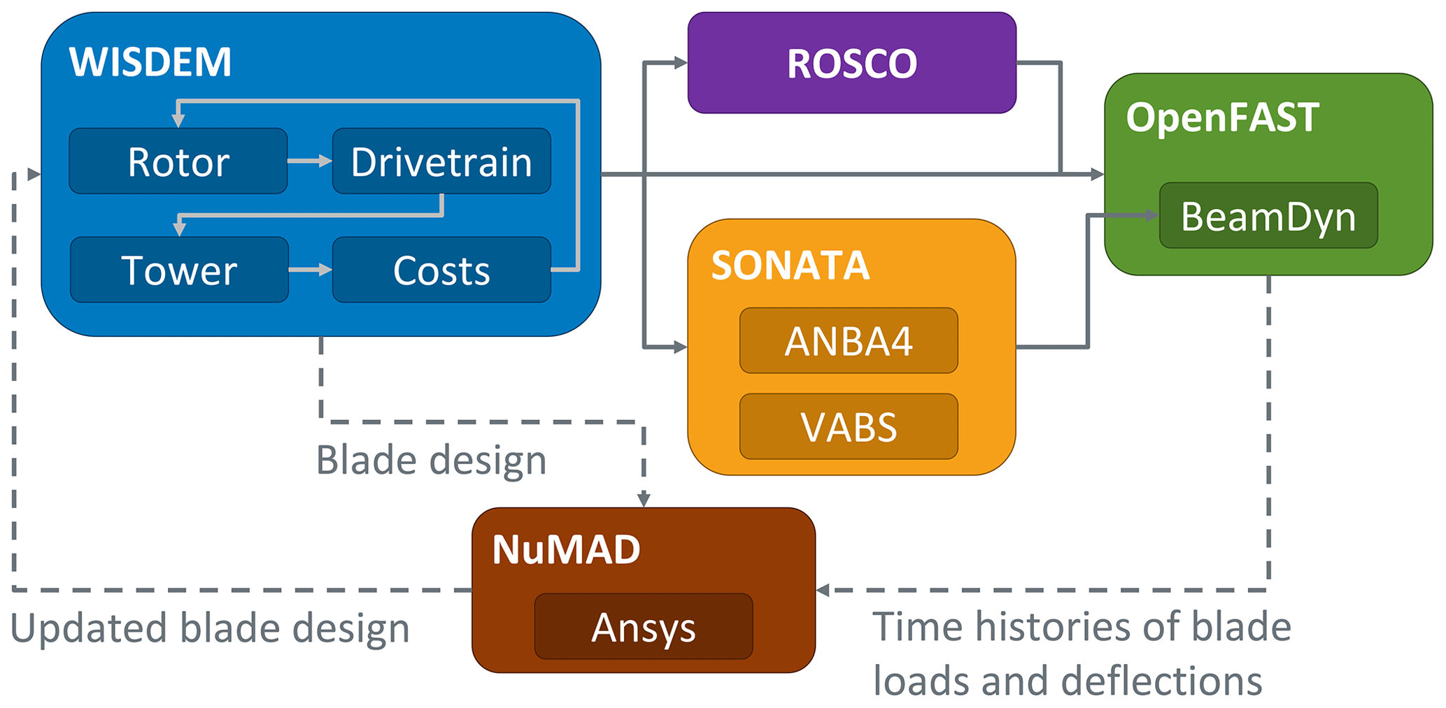
Figure 1Scheme illustrating the sequence of numerical frameworks adopted in this study. WISDEM is described in Sect. 2; and ROSCO, SONATA, and OpenFAST are described in Sect. 3. NuMAD and the data flow to it, which is represented by the dashed line, are described in Camarena et al. (2021).
2.1 Models
WISDEM is made of several components all wrapped by an OpenMDAO interface. The next subsections introduce the models that have been adopted for this study and distinguish among rotor, drivetrain, tower, and models for the cost analysis.
2.1.1 Rotor
WISDEM simulates the rotor with steady-state models. The rotor aerodynamics are solved with the blade element momentum model CCBlade (Ning, 2014); the elastic properties of the composite blades are obtained by running the cross-sectional solver PreComp (Bir, 2006), and the deformations are obtained by running the Timoshenko beam solver Frame3DD (Gavin, 2014). A steady-state regulation trajectory is implemented by maximizing the rotor performance until rated power is reached and by imposing a constant power above the rated wind speed. An optional constraint on the maximum blade tip speed is respected by maximizing power performance while maintaining a constant rotor speed. The AEP is computed here, whereas the ultimate loads are estimated by running a CCBlade simulation at rated pitch and rotor speed values and at a wind speed corresponding to the peak of the three-sigma gust for the extreme turbulence model (IEC-61400-1, 2005; Ning and Petch, 2016). This approach to estimating loads is known to be somewhat overconservative, but it is capable of capturing the relative trends, and it is suitable for running an iterative optimization loop on standard hardware in only a few minutes. The work described in Camarena et al. (2021) shows how the detailed structural design of the blades is clearly necessary, although the simplified loading approach leads to fairly realistic designs that are close to the optimal point.
2.1.2 Drivetrain
This work assumes geared wind turbine configurations, and the engineering models described in Guo et al. (2015) are used to design the various nacelle components. Simplified analytical relations are adopted to size the pitch system, the hub, the main bearings, the low-speed shaft, a three-stage gearbox, the high-speed shaft, the generator, the bedplate, the nacelle cover, a transformer, the yaw bearings and motors, and the auxiliary systems. The components are designed assuming a desired value of the gearbox ratio and overhang, whereas the loading comes from the rotor models described in Sect. 2.1.1.
2.1.3 Tower
The tower is defined as a sequence of conical hollow cylinders made of steel. Within Frame3DD (Gavin, 2014), the tower is modeled as an elastic beam with a point mass at the top. The mass and center of gravity of the rotor nacelle assembly together with the loads at the tower top are fed to the model, which computes values of maximum stresses, natural frequencies, and buckling limits. The ratio of the wall thickness to outer diameter and the rate of change in the wall thickness along the tower height are also computed and can be constrained during the design optimizations.
2.1.4 Cost analysis
Throughout the years, the National Renewable Energy Laboratory has released multiple models that estimate the costs of wind energy. This work combines a detailed blade cost model (Bortolotti et al., 2019a), a model to estimate the costs of the other wind turbine components and the overall turbine capital costs (Fingersh et al., 2006), and a financial model to compute the LCOE (Stehly and Beiter, 2019). Although the costs of some components – mostly in the nacelle – are estimated via semiempirical relations tuned on historical data that are updated every few years, the blade cost model adopts a bottom-up approach and estimates the total costs of a blade as the sum of variable and fixed costs. The former is based on materials and direct labor costs, whereas the latter accounts for the costs from overhead, building, tooling, equipment, maintenance, and capital. The blade cost model simulates the whole manufacturing process, and it has been tuned to estimate the costs of blades ranging from 30 to 100 m in length. Last, the financial model from Stehly and Beiter (2019) is updated yearly and computes the LCOE by modeling an entire wind power plant. In this study, the number of turbines, the power losses resulting from turbine wakes and electrical losses, the balance-of-station costs, and the operational expenditures are assumed to be equal to the values reported in Stehly and Beiter (2019) referring to land-based installations. The values are reported in Table 1.
Table 1Preassumed inputs to the financial model computing the LCOE (Stehly and Beiter, 2019).

Note that the absolute values of costs contain a wide band of uncertainty, but the authors hope that the models can sufficiently capture the relative trends.
2.2 Rail transport of blades
Wind turbine blades are often transported by rail, especially in the United States. Blades are transported rigidly, and the fixtures on the rail cars allow only some amount of lateral sliding. This work removes the assumption of the rigid transport and allows controlled flexing of the blades. The model is described in detail in Carron and Bortolotti (2020) and is briefly summarized here.
The rail transport model simulates the navigation of flatcars through horizontal and vertical curves, ignoring complex scenarios such as S curves and combinations of horizontal and vertical rail curvatures. The model also assumes very low travel speeds and ignores accelerations besides gravity. The root of the blades is assumed to be located at the center of the first flatcar, and the chord is assumed to be aligned in the vertical direction at a zero twist angle; i.e., the trailing edge points upward. The model also assumes that a hydraulic system can move the blade root vertically and can orient the blade axis dynamically during transport to respect horizontal and vertical clearance profiles, which are assumed to be for oversize loads. In addition, there are hydraulic systems along the blade span that are able to let the blade slide while inducing either flapwise or edgewise bending.
The model computes lateral and vertical reaction forces and the wheel flange derailment criterion, which is the ratio between the lateral and vertical forces at the location of the flatcar wheels. Blade strains resulting from bending are considered at the farthest distance from the shear center in the train coordinate system.
Within WISDEM, the rail module is implemented as two sequential nested optimizations: for lateral and for vertical curves. The design variables in the suboptimizations represent the induced loading along the blade span, the angles at the blade root, and the vertical position of the blade root. The two figures of merit of the two optimization problems are the lateral and vertical reaction forces at the blade root. The optimizations are constrained to keep the blade within the clearance profile for the horizontal and vertical curvatures, to limit the strains along the blade span within a maximum allowable 3500 microstrains, to maintain at least 10 % of the gross weight on each flatcar during navigation of summits, and to avoid exceeding the maximum gross rail weight and prevent damage on the tracks during sags. Once the nested optimizer converges, the ratio of lateral to vertical forces is estimated and passed to the outer design loop.
2.3 Materials
The glass fiber composite materials of the blade are selected from the Montana State University Composite Material Database (Mandell et al., 2016), updated to 2019. Biaxial, triaxial, and unidirectional glass laminates are chosen to be as close as possible to industry standards. An industry-reference pultruded carbon fiber laminate is also adopted from the work of Ennis et al. (2019). All laminates are assumed to be infused by standard epoxy resin. Table 2 reports a summary of the mechanical properties and unit costs of the laminates used in the rotor blades. Readers interested in the details of the material properties and costs should refer to the “Data availability” section at the end of this paper.
Table 2Summary of the mechanical properties and unit costs of the composite materials adopted in the blades. E11: longitudinal Young's modulus; E22: transversal Young's modulus; G: shear stiffness modulus.

2.4 Airfoils
The airfoils of the 10 MW IEA Wind Task 37 reference wind turbine (Bortolotti et al., 2019c) are adopted, adding to the list the 18% thick airfoil NACA 63-618. Table 3 reports the list of airfoils at varying relative thicknesses.
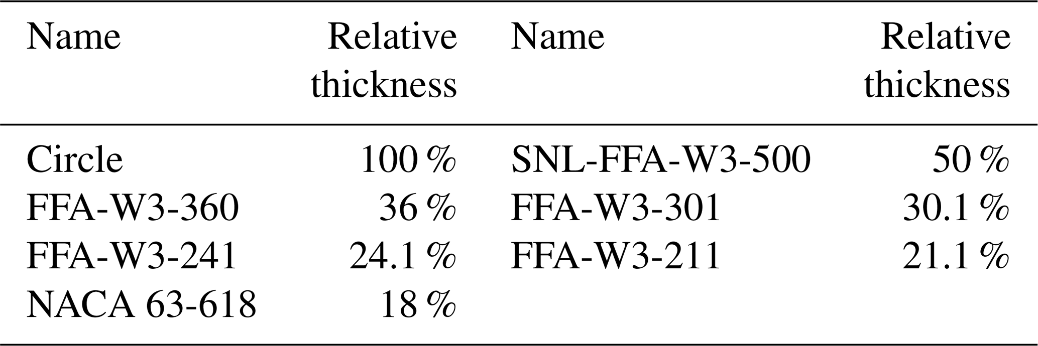
The airfoil polars are computed by running the panel solver XFOIL with default settings, which correspond to free boundary layer transition, estimating the Reynolds and Mach numbers that the airfoils along the blade span experience at rated conditions. XFOIL is run at angles of attack between −10 and 20∘, and outside of this range a Viterna extension is applied. A correction to account for 3D effects is also applied.
The accuracy of the polars is a known shortcoming of the project so far, and one recommendation for future work consists of generating more accurate polars with a higher-fidelity framework.
2.5 Design optimization
This study combines the aerostructural rotor design optimization approach presented in Ning and Petch (2016) with the rail model discussed in Sect. 2.2. The design variables parameterize the blade twist, the chord, the airfoil positions, and the internal thickness of the spar caps at eight stations along the blade span. The design variables at the blade root are kept frozen to avoid unrealistic models of the blade root, whose diameter is preassumed to be equal to 4.5 % of the blade length. Once an optimal chord is found, the chordwise positioning of the sections along the blade span is manually adjusted to have smooth leading and trailing edges and to minimize the offset between the twist axis and the sectional centers of gravity. For each blade, the suction- and pressure-side spar caps have their mid-point placed at the chordwise point of maximum airfoil thickness, whereas their width is optimized in NuMAD (Camarena et al., 2021).
The LCOE is set to be the merit figure to be minimized. In addition, inequality constraints limit the chord to a maximum of 4.5 m; impose a minimum margin to stall of 3∘; limit strains to 3500 microstrains; impose a margin of at least 10 % between the natural frequencies of the blade at the three-per-revolution harmonic of the rotor; and, only for upwind rotors, respect a minimum blade-tower clearance. For the rail transport, an equality constraint imposes that blades have the maximum allowable flapwise stiffness to successfully navigate horizontal curves with a curvature of 13∘. This condition guarantees maximum deployment potential in the interior region of the United States and limited deployment potential in other regions. Vertical curves of up to radii of 2000 ft (610 m) are assumed to be representative of the US main rail network (Carron and Bortolotti, 2020) and do not limit the design of 100 m long blades. In terms of the tip-speed ratio, the study assumes the value of 10.5. This allows for reaching the maximum blade tip speed, which is set at 85 m s−1, immediately before the rated wind speed. The simple calculation assumes a common value of the aerodynamic power coefficient of 0.48.
Sequentially after the rotor design optimizations, a tower design optimization is run to design a realistic tower. The tower design optimization aims to minimize tower mass parameterizing the outer diameter and wall thickness along the tower height. The constraints prevent buckling, violation of ultimate stresses, frequency margins between the first two modes of the tower and the one-per-revolution harmonic of the rotor, unrealistic ratios of diameter to wall thickness, and excessive changes in wall thickness to ensure the feasibility of the hollow steel cylinders.
Once the optimization converges to a design, the input files of the aeroservoelastic solver OpenFAST are automatically generated (NREL, 2021a). The next subsections discuss the models and assumptions behind this process.
3.1 Aerodynamics
OpenFAST implements various models to simulate the aerodynamics of wind turbines (Moriarty and Hansen, 2005). In terms of airfoil aerodynamics, this work adopts the Beddoes–Leishman unsteady model with the Minnema/Pierce variant. The rotor aerodynamics are solved with the combination of blade element momentum theory and the generalized dynamic wake theory, which is used to model skewed and unsteady wake dynamics. Prandtl tip and hub loss models are added to the solutions, whereas the tower wake is modeled via a potential flow model.
Note that these models apply to aerodynamics in the rotor plane and could be inaccurate in the presence of large deflections. The recommendations for future work listed in Sect. 6 suggest a pathway to increase the fidelity level of the rotor aerodynamics.
3.2 Rotor elasticity
In this project, the blade elastic properties were modeled in the submodule ElastoDyn, which implements an Euler–Bernoulli beam formulation, and in the submodule BeamDyn (Wang et al., 2017), which models the three blades with a geometrically exact formulation and requires the 6-by-6 stiffness and inertia matrices.
PreComp (Bir, 2006) implements a modified classic laminate theory with a shear-flow approach, and it is based on shell elements. PreComp offers the attractive advantages of running almost instantaneously and not requiring sophisticated meshing routines; however, it suffers the limitation that it does not estimate the shear stiffness terms. Notably, in WISDEM, Frame3DD is run with no shear and no torsional degree of freedom. In addition, the stiffness and inertia terms computed by PreComp suffer inaccuracies compared to 3D finite-element models (Resor et al., 2010).
A novel open-source framework for the structural analysis of slender composite structures (Feil et al., 2020), named SONATA, was then improved within the BAR project to support the accurate aeroelastic analysis of flexible wind turbine blades. SONATA is adopted here to generate the BeamDyn blade input files. SONATA performs the meshing; performs the 2D and 3D visualizations of the blades; and calls the cross-sectional solvers VABS and ANBA4, which generate identical results except for off-diagonal stiffness terms related to the precurvature of the beam (Feil et al., 2020).
3.3 Controller
The OpenFAST models are controlled via the Reference Open-Source Controller (ROSCO) (Abbas et al., 2021; NREL, 2020). ROSCO implements a pitch control logic with standard rotor speed tracking in above-rated wind speeds and a control logic with optimal tip-speed ratio tracking in below-rated wind speeds, where pitch is held constant. A wind speed estimator based on an extended Kalman filter reconstructs the wind speed at hub height to estimate the current tip-speed ratio. A peak-shaving logic limits rotor thrust to 80 % of the nominal value by pitching before rated power is reached. The blades are controlled via a collective pitch system. Finally, a shutdown logic is implemented; it is described in Sect. 3.3.3.
3.3.1 Tuning
ROSCO is automatically tuned within WISDEM using the ROSCO generic tuning logic (Abbas et al., 2020). The tuning is based on the tip-speed ratio versus pitch angle tables of power, thrust, and torque coefficients that are generated by running a matrix of cases in CCBlade (Ning, 2014). From the tables, the sensitivity of power to changes in pitch angle and rotor speed is reconstructed. The user provides desired closed-loop response characteristics of the rotor for the pitch and torque control actuator tuning procedure, and the corresponding proportional and integral terms of the controller are calculated automatically.
3.3.2 Low pitch rate
A survey among representatives of the wind turbine manufacturing industry returned the concern that very large and flexible wind turbine blades could hit the technological limits of modern pitch systems. This is mainly caused by the large rotational moment of inertia at high deflections. To address this concern, a conservative value of the maximum rate of the pitch actuators is adopted – namely, 2∘ s−1. This low pitch rate limits the response time of the rotor to transient events, such as the occurrence of wind gusts and shutdown maneuvers, resulting in higher loads.
3.3.3 Shutdown
The standard logic of ROSCO triggers a shutdown when a rotor overspeed or a pitch angle beyond the value corresponding to cut-out wind speed is recorded. When the shutdown is triggered, the desired pitch angle is set to 90∘ and the pitch systems are actuated at the maximum rate, whereas the torque actuator attempts to slow the rotor speed to zero in a 30 s time window. Notably, the torque actuator does not necessarily saturate, which can cause higher loads than the softer slowing of the rotor that has been implemented. An additional shutdown trigger has been implemented, where the shutdown procedure is initiated when the filtered signal of the yaw error is higher than 120∘ in average wind speeds greater than 5 m s−1. This condition is not common in operational design load cases, but it helps to limit the ultimate loads generated during the occurrence of extreme changes of wind direction.
Downwind rotors do not eliminate the constraint on minimum tower clearance because downwind rotor blades undergo significant deflections toward the tower in various operating and storm conditions. In this project, the highest deflections have been recorded during emergency shutdown maneuvers below the rated wind speed and during operation at wind speeds close to the cut-out wind speed. The shutdown logic of ROSCO for downwind configurations is then adapted in two ways. First, the cut-out wind speed is reduced from 25 to 19 m s−1. Second, the direction of the pitching maneuver for shutdowns triggered by an extreme change of wind direction at and below rated power is switched from 90 to −90∘ and a pitch-to-stall maneuver is initiated. This operation simultaneously increases lift and drag, and the blades do not flap toward the tower but away from it. A comparison of blade root and tower base bending moments shows smaller values than traditional pitch-to-feather shutdown maneuvers. Notably, the same operation cannot be performed above the rated wind speed because pitching to stall implies crossing the region of angles of attack corresponding to high airfoil efficiencies. Such a procedure would result in higher loads than a conventional pitch-to-feather strategy.
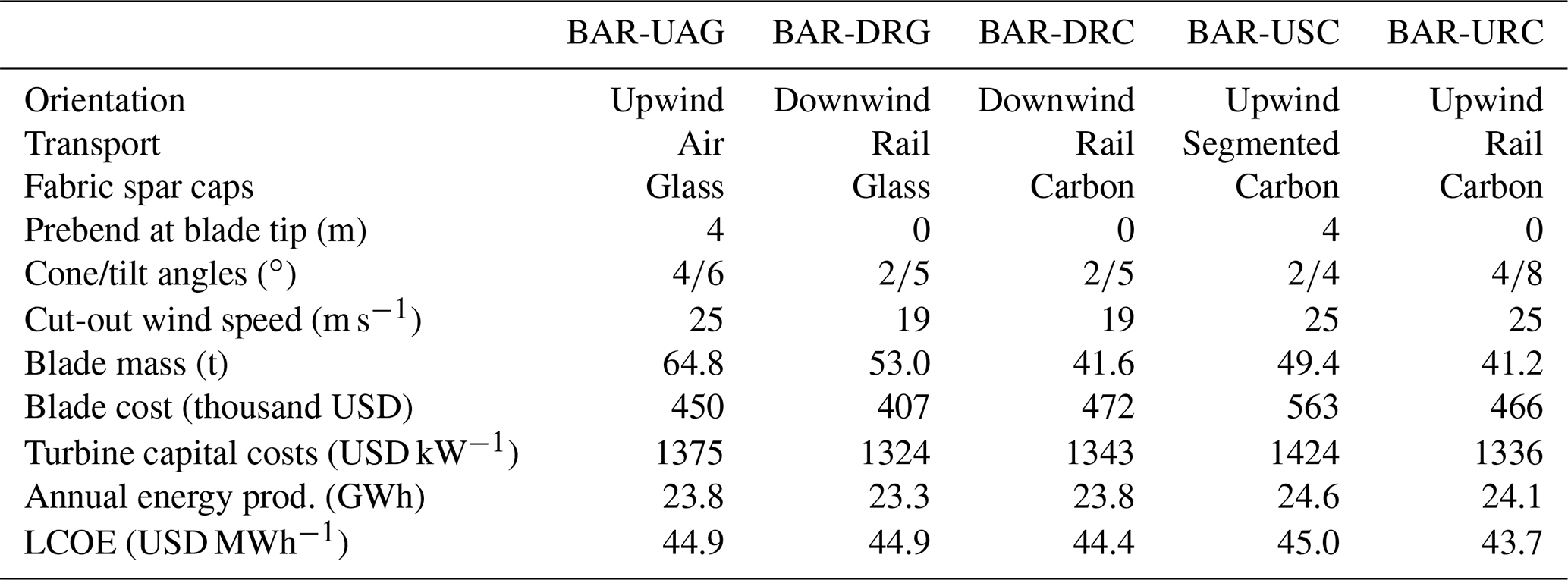
Table 4 lists the five designs that have been developed in this study to run analyses and comparisons. The values reported in the table are discussed in the next sections. All designs are three-bladed and have a rated power of 5 MW, a hub height of 140 m, a rotor diameter of 206 m, and a wind class of 3A (IEC-61400-1, 2005). Blades do not feature any bend–twist coupling technology, such as sweep and fiber misalignment. All blades have successfully completed the high-fidelity structural design optimization described in Camarena et al. (2021). Readers interested in the technical details of the designs can refer to the “Data availability” section and to Johnson et al. (2021).
4.1 Upwind–Air transport–Glass fiber spar caps (BAR-UAG)
The first design, which is named BAR-UAG (Upwind–Air transport–Glass fiber spar caps), is an upwind configuration designed without transportation constraints. BAR-UAG blades could be transported to only a limited number of sites or via some advanced air-shipping technology, which is today not commercially available. This design was developed to demonstrate what a rotor design would look like without logistical constraints and to serve as a baseline by which to compare the other BAR designs. The maximum chord is designed for a minimum LCOE, and it is equal to 5.3 m. This value exceeds the limit to ensure transportability. Notably, this chord distribution is not the aerodynamically optimal one, but larger values incur marginally higher rotor efficiency and higher blade costs, which are mostly caused by higher building and tooling costs, as estimated by Bortolotti et al. (2019a). The prebend of the blade is limited to 4 m for similar blade-manufacturing reasons because higher values of prebend would require special tooling and special infrastructures, such as higher-than-usual assembly lines to open and close the blade molds. The blades have spar caps made of glass fiber laminate. The thickness of the spar caps is driven by the constraint on maximum blade tip deflection, and rotor precone and nacelle uptilt angles are set to 4 and 6∘, respectively, to limit blade mass.
The BAR-UAG design is used to design a reference tower. A design optimization as described in Sect. 2.5 is performed, showing that a standard configuration with a maximum diameter of 4.5 m cannot be designed without violating the constraints, whereas the optimizer converges if the upper bound on the diameters is increased to 6 m. This suggests that – as hinted in the introduction – a novel technological solution such as hybrid concrete–steel or field welding is needed for the concepts developed in this study.
4.2 Downwind–Rail transportable–Glass fiber spar caps (BAR-DRG)
The BAR-DRG wind turbine (Downwind–Rail transportable–Glass fiber spar caps) mounts blades with glass fiber spar caps and meets the rail transportation requirements. Prebend is removed; the maximum chord is limited to 4.75 m, and the design optimization significantly reduces the thickness of the blade spar caps to successfully navigate 13∘ horizontal rail curves. The resulting design is much more flexible than the BAR-UAG blades, with savings in blade mass of 18 %. The limitation of the BAR-DRG rotor is that it can fly only in a downwind configuration to avoid tower strikes. In terms of power performance, two opposite trends coexist. On one hand, the downwind configuration allows for reducing cone and tilt angles. On the other hand, a poorer power performance is generated because of the reduced swept area caused by the blade deflections. The effects on AEP of the cut-out wind speed set at 19 m s−1 are quantified as equal to 0.2 GWh – namely, 0.9 % for the BAR-DRG design. A stiffer rotor design could operate at a higher cut-out wind speed and diminish the power losses, but then it would not comply with the rail transportation requirements.
4.3 Downwind–Rail transportable–Carbon fiber spar caps (BAR-DRC)
The BAR-DRC wind turbine (Downwind–Rail transportable–Carbon fiber spar caps) is an evolution of the BAR-DRG design, where the composite of the spar caps is switched from glass to pultruded carbon fiber (Ennis et al., 2019). Thanks to the much higher longitudinal Young's modulus, see Table 2, carbon allows a much thinner relative thickness distribution along the blade span and savings in blade mass of 22 % compared to the BAR-DRG blade. The blade cost of BAR-DRC is 16 % higher than in BAR-DRG and 5 % higher than in BAR-UAG.
4.4 Upwind–Segmented–Carbon fiber spar caps (BAR-USC)
The BAR-USC design (Upwind–Segmented–Carbon fiber spar caps) models a segmented blade configuration. The blades, which adopt the baseline carbon fiber material listed in Table 2 in the spar caps, mount a joint at 70 % span. The mass and cost of the joint are assumed to be 2000 kg and USD 50 000, respectively. Thanks to the carbon spar caps, the blades, which are prebent as in BAR-UAG, are 24 % lighter than in BAR-UAG despite a maximum chord limited to 4.75 m. The usage of carbon fiber and the presence of the segmentation joint lead to the highest blade costs, namely +25 % and +19 % compared to the BAR-UAG and BAR-DRC blades. The stiffer spar caps, however, allow for reducing the cone and tilt angles to 2 and 4∘, respectively, resulting in a higher rotor-swept area and the highest AEP among the designs, namely 24.6 GWh.
4.5 Upwind–Rail transportable–Carbon fiber spar caps (BAR-URC)
The last design, BAR-URC (Upwind–Rail transportable–Carbon fiber spar caps), is an upwind design with rail-transportable blades made with carbon fiber spar caps. BAR-URC is again straight – i.e., no prebend is present – and the blade is very similar to the BAR-DRC blade. To comply with the tip deflection constraint, the cone and tilt angles of BAR-URC are raised to 4 and 8∘, respectively. In terms of AEP, despite the significantly higher cone and tilt angles, BAR-URC produces slightly more AEP than BAR-DRC, namely +1.3 %. The higher power production is generated by the higher swept area under loading of the upwind design, whereas downwind rotors inherently reduce their swept area when loaded.
All designs are run through a list of design load cases representative of operational, emergency, and storm conditions. The cases 1.1, 1.2, 1.3, 1.4, 1.5, 5.1, 6.1, and 6.3 described by the International Electrotechnical Commission (IEC) standard IEC-61400-1 (2005) are run for every model, with the turbulent wind modeled at six different occurrences. Table 5 shows the load cases considered for the designs. Note that this list represents a subset of the full list of cases prescribed by the standards. Nonetheless, it is in line with other works in the field of systems engineering of wind turbines (Bortolotti et al., 2019b, c; Gaertner et al., 2020). The simulations are performed in OpenFAST with BeamDyn, and the resulting loads are used by Camarena et al. (2021) to run the structural design optimizations. The next sections discuss the aeroservoelastic performance of the designs listed in Table 4 using the loads from Table 5.
Table 5Design load cases (DLCs) included in this study. U: ultimate; F: fatigue; PSF: partial safety factor; WS: wind speed; Vr: rated wind speed; Vin: cut-in wind speed; Vout: cut-out wind speed; V50: 50-year wind speed; V1: 1-year wind speed; NTM: normal turbulence model; ETM: extreme turbulence model; ECD: extreme coherent gust with direction change; EWS: extreme wind shear; EWM: extreme wind model. The details of these design load cases are described in IEC-61400-1 (2005).

5.1 Comparison between PreComp and ANBA4
A comparison of the results generated by PreComp and ANBA4 is first run to verify the accuracy of PreComp and to ensure that the modeling differences between the design process, which is based on PreComp, and the aeroelastic simulations, which are based on ANBA4, are close. The analysis initially considered simple composite beams with a square section, returning minor discrepancies in flapwise and edgewise stiffness and unit mass. Next, the comparison considered the blades described in Sect. 4, showing larger differences. These can be partly attributed to the differences in the meshing logic – i.e., SONATA uses planar elements, whereas PreComp is based on shell elements – and partly to differences between the two solvers.
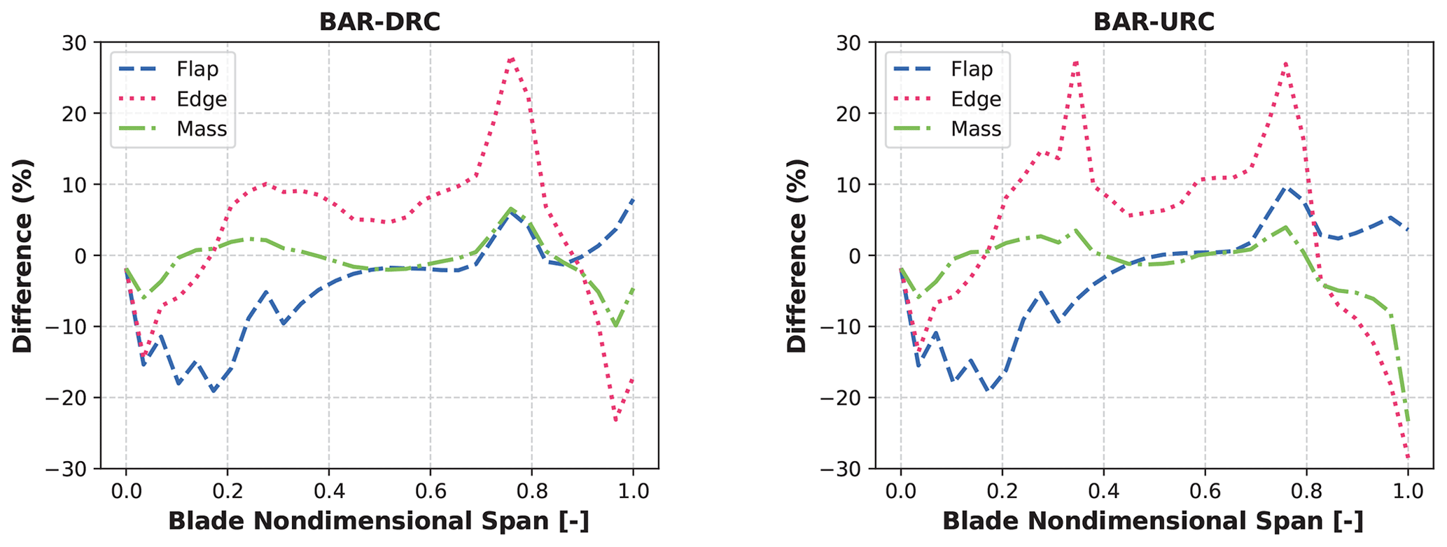
Figure 2Difference in flapwise stiffness, edgewise stiffness, and unit mass distributions between PreComp and ANBA4 for the designs BAR-DRC and BAR-URC. Negative values mean that ANBA4 predicts lower values than PreComp.
Figure 2 reports the comparison in terms of flapwise stiffness, edgewise stiffness, and unit mass distributions between PreComp and ANBA4 for the designs BAR-DRC and BAR-URC. The comparison is found to be somewhat less pessimistic than the one described in Chen et al. (2010), but differences of up to ±20 % in flapwise stiffness and ±30 % in edgewise stiffness are recorded. The differences in the meshing – which explain the discrepancies between ±5 % in the mass distribution – partially explain the differences, but they do not clear them completely. Notably, the BAR-UAG, BAR-DRG, and BAR-USC designs show similar trends.
The comparison also considered the natural frequencies, which are computed by Frame3DD with the two sets of elastic properties. Here, numbers are closer, with the first five modes within a 3 % difference, whereas larger discrepancies are observed for the modes above the fifth. Overall, the comparison concludes that PreComp can be adopted as a conceptual design tool, but higher-fidelity structural solvers such as ANBA4 are recommended for a detailed design step.
5.2 Loads and deflections ranking
The second step of the analysis consisted of ranking the loads and the blade deflections. The results for the blade deflections toward and away from the tower are shown in Fig. 3. For the upwind designs, the highest out-of-plane blade tip deflections toward the tower are measured during operational load cases at and above the rated wind speed – namely, design load case (DLC) 1.3 at 11 m s−1 for BAR-UAG, DLC 1.3 at 23 m s−1 for BAR-USC, and DLC 1.3 at 23 m s−1 for BAR-URC. Note that BAR-URC has marginally smaller deflections than BAR-UAG, but the nacelle uptilt angle is higher to compensate for the zero prebend; see Table 4. All three designs have a very flat ranking, with several design load cases generating similar ultimate deflections. In terms of deflections away from the tower, all three designs record the highest values during an extreme gust with direction change – namely, DLC 1.4 at 6.3 m s−1.

Figure 3Ranking of the out-of-plane blade deflections for the BAR designs. Deflections are aligned with the primary wind direction, so deflections toward the tower are positive in upwind rotors (BAR-UAG, BAR-USC, and BAR-URC) and negative in downwind rotors (BAR-DRG and BAR-DRC). The colors represent the different design load cases (DLCs) listed in Table 5. The deflections do not include partial safety factors.
For the downwind designs, the highest out-of-plane blade tip deflections toward the tower occur during operation or during a shutdown event occurring close to the cut-out wind speed – namely, DLC 1.3 and DLC 5.1 at 19 m s−1. Notably, deflections toward the tower would be higher if the cut-out wind speed were higher. Away from the tower, the highest deflections occur during the extreme gust with direction change, namely DLC 1.4 at 10.3 m s−1. BAR-DRG reaches a blade deflection of 19 m, whereas BAR-DRC has a maximum blade deflection of 16 m. These high deflections would cause a tower strike with a standard shutdown maneuver based on a pitch-to-feather strategy; see Sect. 5.3. With the pitch-to-stall strategy, the design drivers become ultimate loads, as discussed in Camarena et al. (2021).
In terms of blade flapwise loads, the rankings follow those of the blade deflections. The ranking of fore-aft tower base moments is reported in Fig. 4. DLC 1.4 causes the maximum moments for all designs, with the heavier (BAR-UAG and BAR-DRG) and the most efficient (BAR-USC) designs suffering the highest moments. BAR-URC records the lowest moments, equal to 198 MN m, followed by BAR-DRC at 235 MN m.

5.3 Shutdown of downwind
The extreme gust with direction change – namely, DLC 1.4 – is found to generate the highest blade deflections and loads; however, the loads and deflections of the flexible downwind rotors BAR-DRG and BAR-DRC would have been higher without the pitch-to-stall strategy applied at and below the rated wind speed, as described in Sect. 3.3.3. Figure 5 shows the time histories of the pitch angle, the flapwise tip deflection of Blade 1, the flapwise root moment of Blade 1, and the fore-aft tower base moment for the pitch-to-feather and pitch-to-stall maneuvers for the BAR-DRC design during an extreme gust with change of direction.
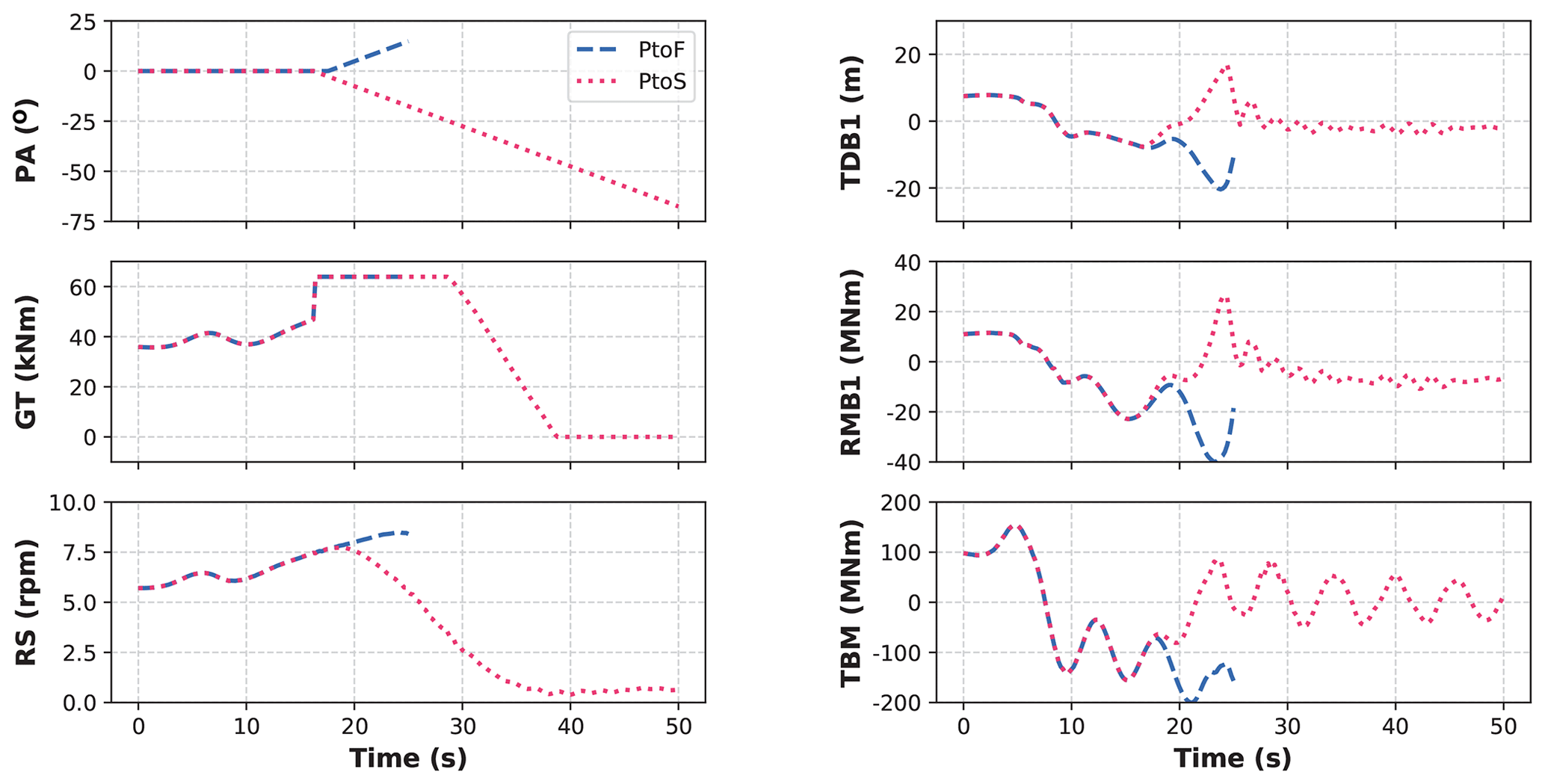
Figure 5Comparison of the time histories of pitch angle (PA) in degrees, generator torque (GT) in kilonewton meters, rotor speed (RS) in revolutions per minute, flapwise tip deflection of Blade 1 (TDB1) in meters, flapwise root moment of Blade 1 (RMB1) in meganewton meters, and fore-aft tower base moment (TBM) in meganewton meters for the pitch-to-feather (PtoF) and pitch-to-stall (PtoS) maneuvers for the BAR-DRC design during an extreme gust with a change of direction. The PtoF maneuver is interrupted at 25 s because of a tower-strike event of Blade 2.
The time histories show lower blade deflection and lower blade and tower moments for the pitch-to-stall maneuver, whereas the pitch-to-feather maneuver leads to a tower strike of Blade 2 at second 25. Note that the this maneuver pushes the angles of attack along the blade span into the deep stall region, which is not very well characterized numerically. Higher-fidelity simulations and field tests are recommended to verify and validate this approach to shutdown.
5.4 Torsional deformations and power performance
Increasing the flexibility of the wind turbine rotors leads to increased torsional deformations of the outer blade portions. Figure 6 reports a comparison at varying wind speeds among all five designs at 79 % span and at the blade tip measured during six occurrences of DLC 1.1. The torsional deformations increase in the rail-transportable designs, especially in the BAR-URC design, which often sees 1 extra degree of torsional rotation compared to the jointed blade BAR-USC. Simplified beam models that do not model the torsional degree of freedom, such as the one implemented in ElastoDyn, are not accurate enough to capture the aeroelastic response of slender wind turbine blades, such as the ones investigated here.
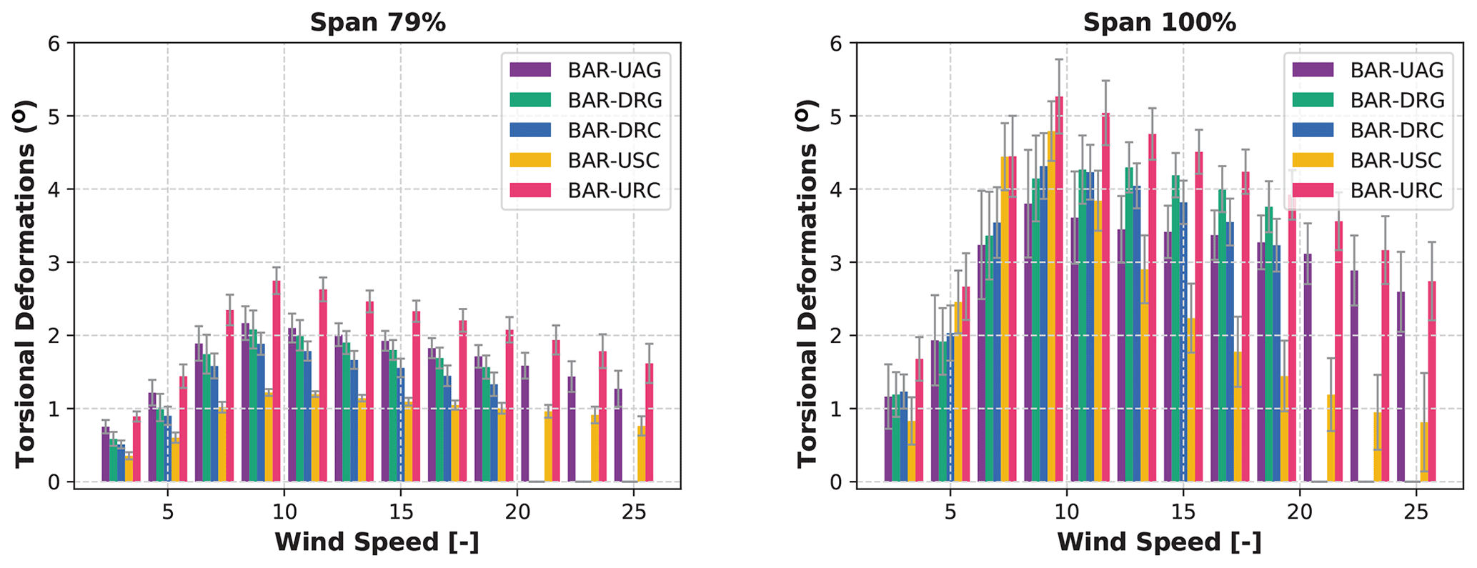
Figure 6Average torsional deformations at 79 % blade span and at the blade tip at varying wind speeds during six occurrences of DLC 1.1. The error bars indicate the standard deviation.
The annual power production is computed by integrating the generator power along six 10 min simulations with the normal turbulence model at wind speeds spaced by 2 m s−1 between the cut-in and cut-out wind speeds. The power curve is weighted with the Weibull distribution for a Class-3 wind turbine. Note that the results of such an approach are affected by the control tuning, which could slightly vary among designs. The analysis was therefore repeated for steady-state inflow wind conditions, and although the results were different in the absolute values, the trends were found to match.
Despite the high values of torsional deformations, the power performance of the various rotors is not dramatically different; however, two trends are still visible. First, carbon fiber designs support thinner airfoils along the blade span and allow for more efficient designs. BAR-USC generates 3.4 % higher AEP than BAR-UAG, whereas BAR-DRC generates 2.1 % higher AEP than BAR-DRG. Second, flexible downwind wind turbines generate less power than equivalent flexible upwind configurations. Qualitatively, this trend can be explained by the lower cut-out wind speed of the downwind rotors and by the fact that when loaded, upwind blades increase the rotor-swept area, whereas the opposite holds true for downwind designs. This trend can be mitigated with stiffer downwind rotors with smaller cone and tilt values, but at equal conditions the LCOE of downwind rotors is likely higher than that of upwind rotors. BAR-DRC, although mounting very similar blades and significantly smaller cone and tilt angles, generates 1.2 % less AEP than BAR-URC, which in turns generates 2.0 % less AEP than BAR-USC.
5.5 LCOE
The study concludes with a discussion about the values listed in Table 4 of turbine capital costs and the levelized cost of wind energy of the various designs. All designs are found to generate similar values of the LCOE, with BAR-DRC and BAR-URC generating the best compromise between AEP and turbine capital costs. Compared to BAR-DRG, BAR-DRC compensates for the higher blade costs with higher power production generated by the thinner airfoils. The comparison of the values of the LCOE returns a 1.1 % lower value for the BAR-DRC design compared to the BAR-DRG design. For the upwind configurations, the advantages generated by the lighter BAR-URC rotor lead to a 2.9 % saving in the LCOE compared to the jointed design BAR-USC. In terms of capital costs, the flexible rotor designs BAR-DRG, BAR-DRC, and BAR-URC achieve the lowest numbers thanks to low blade costs and system savings generated by the lighter rotors. BAR-DRG reports the lowest value, USD 1324 kW−1, closely followed by BAR-DRC and BAR-URC with USD 1343 kW−1 and USD 1336 kW−1. Note again that these numbers suffer from a wide band of uncertainty and could vary from one manufacturer to another and from one site to another. Also, all designs adopt the same tower, which is designed for BAR-UAG and is likely too heavy and expensive for all other four designs, with the possible exception of BAR-USC. It is clearly shown, however, that highly flexible rotors not only help address logistics constraints but also can lead to savings in the LCOE.
This work presents the research activities focused on designing novel land-based wind turbines whose blades can be transported by rail via controlled bending. The studies are conducted on a 5 MW platform with a rotor diameter of 206 m and a hub height of 140 m. The activities fall within the BAR project funded by the US Department of Energy and show a promising pathway toward very flexible wind turbine rotors. The three key conclusions of the work are as follows:
-
Controlled bending during rail transportation of both upwind and downwind rotor blades of 100 m in length represents a promising pathway to increasing the size of land-based wind turbines. Longer blades could be adopted – both upwind and downwind – by exceeding conventional values of rotor cone and nacelle uptilt angles.
-
Downwind turbines with flexible rotor blades suffer the risk of running into blade-tower strikes; however, blade deflections toward the tower can be alleviated by reducing the cut-out wind speed and implementing a pitch-to-stall strategy for shutdown maneuvers at and below the rated wind speed.
-
The use of pultruded carbon fiber in the spar caps leads to slightly more expensive blade designs but also higher aerodynamic performance and lower systems costs, ultimately reducing the LCOE compared to standard glass fabrics.
The recommended activities can be summarized into five main areas:
-
The airfoil polars adopted in this study should be replaced with a mix of free transition and fully turbulent polars generated by 2D computational fluid dynamics. Such a framework has only recently become available to the authors and will be used to replace the outputs from XFOIL, which can be seen only as a conceptual design tool. The airfoil polars at a high Reynolds number should also be validated against experimental data. Although this second step would represent a major improvement to the quality of this work, the lack of good-quality data in the public domain to validate airfoil aerodynamics is an obstacle that is hard to overcome, and it is currently seen as a strong limitation for the whole research community.
-
The aerodynamics of the flexible rotors should be investigated at higher fidelity, through vortex-based aerodynamic models and blade-resolved computational fluid dynamics. The performance of the highly coned and tilted upwind rotor should also be checked. Validation studies are ongoing with the vortex model implemented in OpenFAST and described in Shaler et al. (2020). The pitch-to-stall shutdown maneuver should also be the topic of a dedicated investigation.
-
Downwind wind turbines have historically suffered from low-frequency noise generation and higher fatigue damage because of the blades passing in the wake of the tower. Preliminary analysis has increased confidence that the issues might have affected old wind turbines more than modern configurations (Bertagnolio et al., 2019), but a final answer is yet to be made.
-
The tuning of the controller should be optimized taking into account the complex aeroelastic behavior of the flexible rotors. Also, the controller of the downwind rotors could be tuned more accurately, exploring new logic to maximize power and minimize deflections toward the tower. One possible pathway consists of maintaining a standard cut-out wind speed and implementing a derating, which would minimize AEP losses while preventing the blade from flying too close to the tower. Highly flexible blades could also benefit from distributed aerodynamic control devices more than traditional blades. Several research projects are ongoing in this field and should continue.
-
This study has adopted WISDEM and OpenFAST, which are characterized by two different levels of fidelity. Work is ongoing to adopt formal approaches for the multifidelity optimization of wind turbines (Jasa et al., 2021).
All codes used within this work are publicly available. WISDEM is available at https://github.com/WISDEM/WISDEM (NREL, 2021b); OpenFAST is available at https://github.com/OpenFAST/openfast (NREL, 2021a), and ROSCO is available at https://github.com/NREL/ROSCO (NREL, 2020). These tools have recently been integrated into a single framework named WEIS, which can be accessed at https://github.com/WISDEM/WEIS (NREL, 2021c). Last, SONATA is available at https://gitlab.lrz.de/HTMWTUM/SONATA (TUM, 2021).
The five wind turbine designs developed in this work are available at https://github.com/NREL/BAR_Designs (NREL, 2021d) as OpenFAST models equipped with the ROSCO controller and as input files to WISDEM and WEIS. The latter files respect the wind turbine ontology windIO, which is developed within the IEA Wind Task 37 on systems engineering. The documentation of windIO is available at https://github.com/IEAWindTask37/windIO (IEA Wind Task 37, 2021).
PB led the wind turbine design process and the preparation of this paper. NJ leads the Big Adaptive Rotor project and helped with all tasks. NJA was in charge of the control development and control tuning. EA and EC led the detailed structural design of the blades. JP co-leads the entire Big Adaptive Rotor project and provided countless inputs. All six authors provided valuable feedback and guidance throughout the entire study.
The authors declare that they have no competing interests in executing and publishing this work.
The views expressed in the article do not necessarily represent the views of the DOE or the US Government. The US Government retains and the publisher, by accepting the article for publication, acknowledges that the US Government retains a nonexclusive, paid-up, irrevocable, worldwide license to publish or reproduce the published form of this work, or allow others to do so, for US Government purposes.
This paper describes objective technical results and analysis. Any subjective views or opinions that might be expressed in the paper do not necessarily represent the views of the US Department of Energy or the United States Government.
Publisher’s note: Copernicus Publications remains neutral with regard to jurisdictional claims in published maps and institutional affiliations.
The authors acknowledge the valuable input provided during the writing of this paper. The authors are grateful to the whole Big Adaptive Rotor team across the four national laboratories active in BAR and to the OpenFAST and the WISDEM teams at the National Renewable Energy Laboratory. The feedback, guidance, and review from all team members are greatly appreciated. The inputs of the advisory panel throughout the design process of the Big Adaptive Rotor turbines were also extremely valuable. Finally, the input of the two reviewers Athanasios Barlas and Didier Lemosse is acknowledged.
A portion of the research was performed using computational resources sponsored by the US Department of Energy's Office of Energy Efficiency and Renewable Energy and located at the National Renewable Energy Laboratory.
This work was authored in part by the National Renewable Energy Laboratory, operated by the Alliance for Sustainable Energy, LLC, for the US Department of Energy (DOE) under contract no. DE-AC36-08GO28308. Funding was provided by the US Department of Energy's Office of Energy Efficiency and Renewable Energy Wind Energy Technologies Office. Sandia National Laboratories is a multimission laboratory managed and operated by National Technology & Engineering Solutions of Sandia, LLC, a wholly owned subsidiary of Honeywell International Inc., for the US Department of Energy's National Nuclear Security Administration under contract DE-NA0003525.
This paper was edited by Sandrine Aubrun and reviewed by Athanasios Barlas and Didier Lemosse.
Abbas, N., Zalkind, D., Pao, L., and Wright, A.: A Reference Open-Source Controller for Fixed and Floating Offshore Wind Turbines, Wind Energ. Sci. Discuss. [preprint], https://doi.org/10.5194/wes-2021-19, in review, 2021. a
Abbas, N. J., Wright, A., and Pao, L.: An Update to the National Renewable Energy Laboratory Baseline Wind Turbine Controller, J. Phys. Conf. Ser. 1452, 012002, https://doi.org/10.1088/1742-6596/1452/1/012002, 2020. a
Bertagnolio, F., Madsen, H. A., and Fischer, A.: Analysis of low-frequency noise from wind turbines using a temporal noise code, Proceedings of the 23rd International Congress on Acoustics, Aachen, Germany, 9 Sep 2019–13 September 2019, 4414–4421, 2019. a
Bir, G. S.: User’s Guide to PreComp (Pre-Processor for Computing Composite Blade Properties), Tech. rep., National Renewable Energy Laboratory, https://doi.org/10.2172/876556, 2006. a, b
Bolinger, M., Lantz, E., Wiser, R., Hoen, B., Rand, J., and Hammond, R.: Opportunities for and challenges to further reductions in the “specific power” rating of wind turbines installed in the United States, Wind Engineering, 45, 351–368, https://doi.org/10.1177/0309524X19901012, 2020. a
Bortolotti, P., Berry, D., Murray, R., Gaertner, E., Jenne, D., Damiani, R., Barter, G., and Dykes, K.: A Detailed Wind Turbine Blade Cost Model, Tech. rep., National Renewable Energy Laboratory, https://doi.org/10.2172/1529217, 2019a. a, b
Bortolotti, P., Bottasso, C. L., Croce, A., and Sartori, L.: Integration of multiple passive load mitigation technologies by automated design optimization—The case study of a medium-size onshore wind turbine, Wind Energy, 22, 65–79, https://doi.org/10.1002/we.2270, 2019b. a, b, c
Bortolotti, P., Tarres, H. C., Dykes, K., Merz, K., Sethuraman, L., Verelst, D., and Zahle, F.: IEA Wind Task 37 on Systems Engineering in Wind Energy – WP2.1 Reference Wind Turbines, Tech. rep., International Energy Agency, https://doi.org/10.2172/1529216, 2019c. a, b
Camarena, E., Anderson, E., Paquette, J., Bortolotti, P., Feil, R., and Johnson, N.: Land-based wind turbines with flexible rail transportable blades – Part II: 3D FEM design optimization of the rotor blades, Wind Energ. Sci. Discuss. [preprint], https://doi.org/10.5194/wes-2021-74, in review, 2021. a, b, c, d, e, f, g
Carron, W. S. and Bortolotti, P.: Innovative rail transport of a supersized land-based wind turbine blade, J. Phys. Conf. Ser., 1618, 042041, https://doi.org/10.1088/1742-6596/1618/4/042041, 2020. a, b
Chen, H., Yu, W., and Capellaro, M.: A critical assessment of computer tools for calculating composite wind turbine blade properties, Wind Energy, 13, 497–516, https://doi.org/10.1002/we.372, 2010. a
Dykes, K., Damiani, R., Roberts, O., and Lantz, E.: Analysis of Ideal Towers for Tall Wind Applications, 2018 Wind Energy Symposium, 8–12 January 2018, Kissimmee, Florida, https://doi.org/10.2514/6.2018-0999, 2018. a
Ennis, B. L., Kelley, C. L., Naughton, B. T., Norris, B., Das, S., Lee, D., and Miller, D.: Optimized Carbon Fiber Composites in Wind Turbine Blade Design, Tech. rep., Sandia National Laboratories, https://doi.org/10.2172/1592956, 2019. a, b
Feil, R., Pflumm, T., Bortolotti, P., and Morandini, M.: A cross-sectional aeroelastic analysis and structural optimization tool for slender composite structures, Compos. Struct., 253, 112755, https://doi.org/10.1016/j.compstruct.2020.112755, 2020. a, b
Fingersh, L. J., Hand, M., and Laxson, A.: Wind Turbine Design Cost and Scaling Model, Tech. rep., National Renewable Energy Laboratory, https://doi.org/10.2172/897434, 2006. a
Gaertner, E., Rinker, J., Sethuraman, L., Zahle, F., Anderson, B., Barter, G., Abbas, N., Meng, F., Bortolotti, P., Skrzypinski, W., Scott, G., Feil, R., Bredmose, H., Dykes, K., Sheilds, M., Allen, C., and Viselli, A.: Definition of the IEA 15 MW Offshore Reference Wind Turbine, Tech. rep., International Energy Agency, https://doi.org/10.2172/1603478, 2020. a, b
Gavin, H. P.: Frame3DD, available at: http://frame3dd.sourceforge.net/ (last access: September 2021), 2014. a, b
Gray, J. S., Hwang, J. T., Martins, J. R. R. A., Moore, K. T., and Naylor, B. A.: OpenMDAO: An open-source framework for multidisciplinary design, analysis, and optimization, Struct. Multidiscip. O., 59, 1075–1104, https://doi.org/10.1007/s00158-019-02211-z, 2019. a
Griffin, D. A., Starnes, S., Smith, K. J., and McCoy, T. J.: R&D Pathways for Supersized Wind Turbine Blades, Tech. rep., Lawrence Berkeley National Laboratory, https://doi.org/10.2172/1498695, 2019. a, b
Guo, Y., Parsons, T., King, R., Dykes, K., and Veers, P.: An Analytical Formulation for Sizing and Estimating the Dimensions and Weight of Wind Turbine Hub and Drivetrain Components, Tech. rep., National Renewable Energy Laboratory, https://doi.org/10.2172/1215033, 2015. a
IEA Wind Task 37: WindIO, v1.0, GitHub [data set], available at: https://github.com/IEAWindTask37/windIO, last access: 20 September 2021. a
IEC-61400-1: Wind turbines – Part 1: Design requirements, Standard, International Electrotechnical Commission, Geneva, CH, 2005. a, b, c, d
Jasa, J., Bortolotti, P., Zalkind, D., and Barter, G.: Effectively using multifidelity optimization for wind turbine design, Wind Energ. Sci. Discuss. [preprint], https://doi.org/10.5194/wes-2021-56, in review, 2021. a
Johnson, N., Paquette, J., Bortolotti, P., Ennis, B., Bolinger, M., Camarena, E., and Anderson, E.: BAR Phase I Final Report, Tech. rep., National Renewable Energy Laboratory, 2021. a
Mandell, J. F., Samborsky, D. D., Miller, D. A., Agastra, P., and Sears, A. T.: Analysis of SNL/MSU/DOE Fatigue Database Trends for Wind Turbine Blade Materials, 2010–2015, Tech. rep., Sandia National Laboratories, https://doi.org/10.2172/1431256, 2016. a
Moriarty, P. J. and Hansen, A.: AeroDyn Theory Manual, Tech. rep., National Renewable Energy Laboratory, https://doi.org/10.2172/15014831, 2005. a
Ning, A. and Petch, D.: Integrated design of downwind land-based wind turbines using analytic gradients, Wind Energy, 19, 2137–2152, https://doi.org/10.1002/we.1972, 2016. a, b, c
Ning, S. A.: A simple solution method for the blade element momentum equations with guaranteed convergence, Wind Energy, 17, 1327–1345, https://doi.org/10.1002/we.1636, 2014. a, b
NREL: ROSCO, Version 2.1.1, GitHub [code], available at: https://github.com/NREL/rosco (last access: 8 April 2021), 2020. a, b
NREL: OpenFAST, v2.5.0, GitHub [code], available at: https://github.com/OpenFAST/openfast (last access: 8 April 2021), 2021a. a, b
NREL: WISDEM, v3.2.0, GitHub [code], available at: https://github.com/WISDEM/WISDEM (last access: 8 April 2021), 2021b. a, b
NREL: WEIS, v0.1, GitHub [code] available at: https://github.com/WISDEM/WEIS (last access: 8 April 2021), 2021c. a
NREL: BAR Designs, v1.0, GitHub [data set], available at: https://github.com/NREL/BAR_Designs, last access: 20 September 2021d. a
Resor, B., Paquette, J., Laird, D., and Griffith, D. T.: An Evaluation of Wind Turbine Blade Cross Section Analysis Techniques, AIAA 2010-2575, https://doi.org/10.2514/6.2010-2575, 2010. a
Shaler, K., Branlard, E., and Platt, A.: OLAF User’s Guide and Theory Manual, Tech. rep., National Renewable Energy Laboratory, https://doi.org/10.2172/1659853, 2020. a
Stehly, T. and Beiter, P.: 2018 Cost of Wind Energy Review, Tech. rep., National Renewable Energy Laboratory, https://doi.org/10.2172/1581952, 2019. a, b, c, d
TUM: SONATA, v0.4.0, GitHub [code], available at: https://gitlab.lrz.de/HTMWTUM/SONATA, last access: 8 April 2021. a
Wang, Q., Sprague, M. A., Jonkman, J., Johnson, N., and Jonkman, B.: BeamDyn: a high-fidelity wind turbine blade solver in the FAST modular framework, Wind Energy, 20, 1439–1462, https://doi.org/10.1002/we.2101, 2017. a